40K HOBBY: One Meks Step-by-Step Guide to Lootin’ – Part Three
8 Minute Read
Dec 26 2011
Advertisement
Continuing my step-by-step part one and two post on how I Loot vehicles, part three follows the second and third Looted Wagons covering their hull re-builds turrets. Also, lots of finished pics!
Looted Wagon 2
Referencing the mock up I lengthened the hull by adding a horizontal panel notched to fit around the detailing on the track units. Some cut down H beams provide some detailing and support. An upright panel was added using engineers squares and internal support to keep it straight.
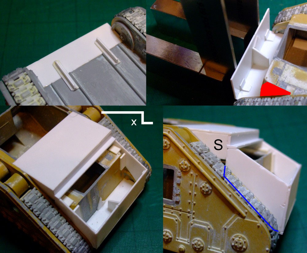
At each corner of the Russ hull 2mm thick sections were cut out with a razor saw, continued down until it passes behind the track unit (red).
A top panel was cut and some 1×4 strip was glued at one end (x). The panel was temporarily fitted in position. The rear side panels were cut and fitted so they ran from the rear panel and angled up to meet the top. A steel ruler allowed me to get the width and height required for these panels. As I removed the section of the hull previously I I only needed cut the panels so the bottom of them would be hidden behind the track units (blue line). It was then a simple matter to add the side panels (s) and glue the top panel in place.
Track guards were added but the cover was left off except for the front as this time the guards will be incorporated into the hull. A panel was added at the rear with the top flush with the top of the track guard ‘walls’.
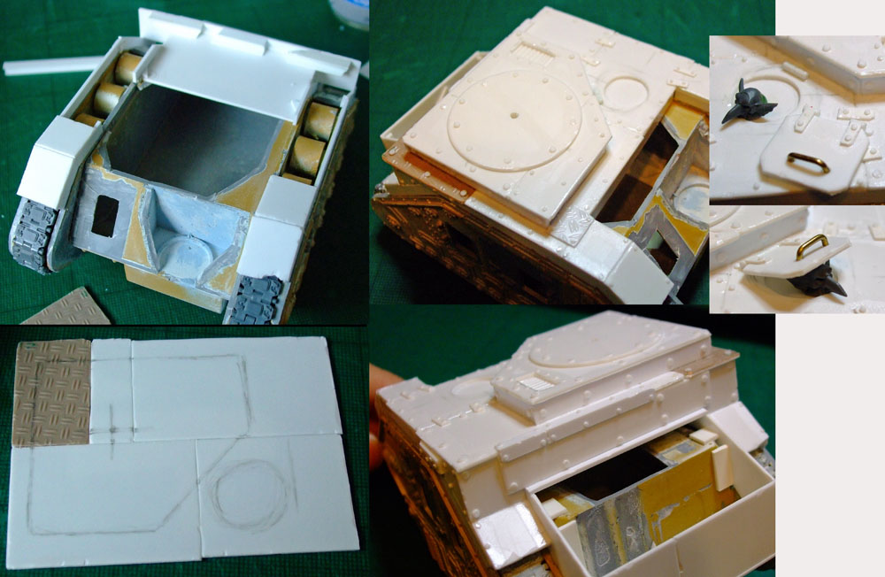
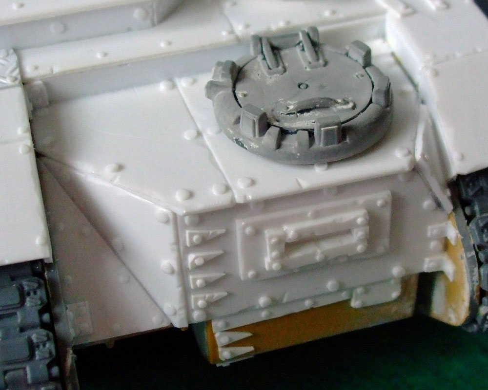
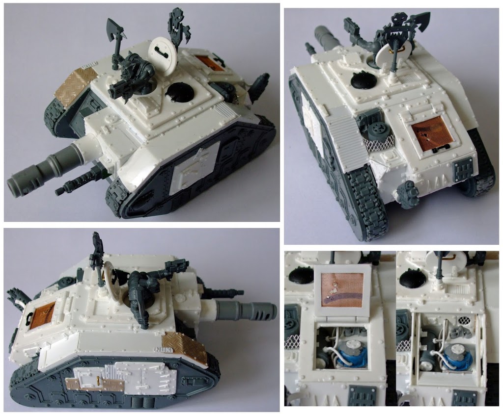
A top panel was cut out and split into sections with one piece replaced with treadplate. I marked on the panel where the offset turret will be going and the area to be built up also a circle where a hatch will go.
The area was built up with a ‘wall’ of 1x4mm strip before a top was added incorporating a vent, a 2mm hole was drilled in line with the turret centre mark. A disc was cut by scoring sheet with a circle cutter and snapping the unwanted material away; the centre was drilled and the disc glued in place.
A circle was cut out with styrene glued on the underside to allow a cut down grots head to be fitted. A small hatch was then made but not glued in place.
The top assembly was fitted and detailed up. At the rear some plating and the rear track guard pieces were added.
The original exhausts were cleaned up and the ends replaced with two thin pieces of 6.3mm tube. For the end pieces 4.8mm tube was cut at 45 degrees before being glued together to form an ‘L’ with GS used on the join. After gluing in place some Orky repair work and rivets were added. The rear was then finished off.
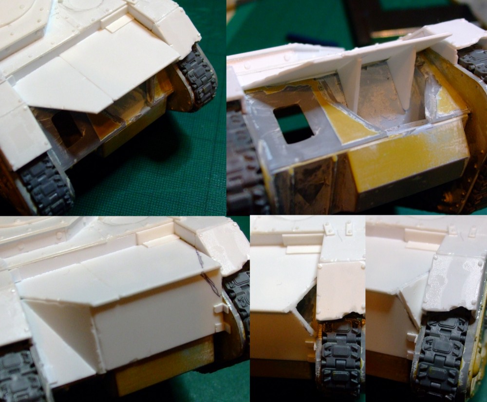
At the front a new drivers cab was needed. The cab top panel was cut and fitted with supports glued underneath to keep the panel in place.
Front and side panels were then cut to suit and fitted. I decided to remove the marked corner using a razor saw. Once cleaned up a small panel was fitted.
The cab was detailed with various dags, rivets and brackets. A vision slit was added using offcuts and the cupola from the original turret was fitted.
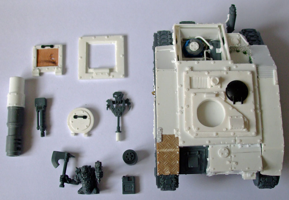
I took the Russ turret and cleaned it up and remove anything I didn’t want. It was then glued down onto styrene which was larger by a 2-3mm.
The centre was measured and a 2mm hole drilled. I glued some metal washers inside to help balance it out and remain in place when fitted.
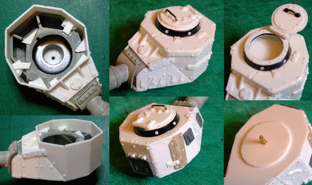
A 20mm wide strip was cut and from this strip I cut panels to go around the turret, glued down onto the styrene base. Offcuts were used to reinforce as required. More styrene panels were added to the front. Once the panels around the turret were done the styrene base was trimmed back and styrene was fitted inside, the krewman will later sit down on this.
The turret was finished off with a top plate incorporating an old 25mm base as a cupola. A disc was added to the underside of the turret and a 2mm brass rod was glued into the hole.
Looted Wagon 3
The simplest of the three, plating was added to the hull with the only real hull modifications being new exhausts and a reinforced ram.
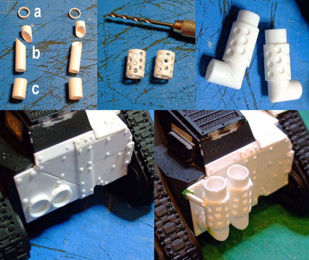
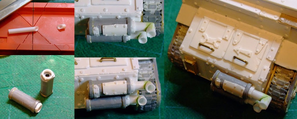
For the exhausts I cut the following: mounting rings (a – 8.7mm), top and lower exhaust pipes (b – 7.1mm) and the exhaust covers (c – 8.7mm).
The covers were drilled before being cleaned up and distressed.
Once the upper and lower exhausts were glued together as ‘L’ shapes and distressed the covers were added.
The two mounting rings were glued to the already detailed rear of the tank and the two exhausts were fitted into them. A couple of support brackets were later added.
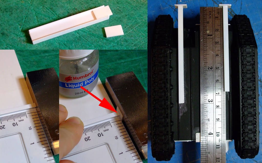
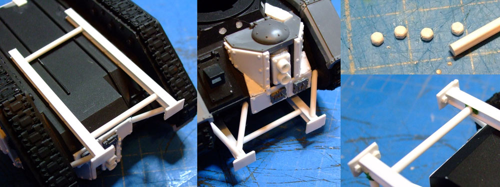
I began on the reinforced ram by making the mounting steelwork. I first cut some styrene 6mm high to fit into the ‘I’ of some 7.9mm I beam. These are the mounting plates onto which the ram will be attached.
4mm ‘H’ Beam was cut into two lengths, approx 65 & 75mm. A mounting plate needed to be attached to one end of each beam. One end was squared off and then lined up with the edge of some 1mm styrene sheet using a set square as shown.
A mounting place was butted up against the end of the beam, as the plate is 2mm taller the 1mm sheet locates the plate centrally. A small amount of glue was applied to the top joint – enough to join them without inadvertently gluing the beam & plate to the sheet. Once lifted clear more glue was added.
Each completed beam was glued to the tank hull up against a ridge; a steel ruler was used to ensure the mounting plates lined up with each other. Finally rivets were added to the beams.
Support pieces made from 2mm rod were glued between the two beams and from the beams to the front of the hull, to make everything look more substantial.
Some hex rod was used to make small bolt heads. Before cutting the six corners at the end were rounded off with some fine wet and dry sandpaper. Approximately 2mm thick piece was then cut off. I used the Chopper tool so I could four pieces the same height. Alternatively a piece could be sawn and sanded back to the height required.
The bolt heads were glued to the mounting plates so the rounded corners face the tank hull.
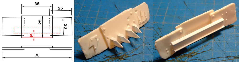
For the ram I cut six pieces of 1mm styrene which were glued together in pairs to give me three pieces 2mm thick. After heavily distressing they were glued together in the arrangement shown so the overall length (x) is approximately the tank width. On the rear 7.9mm I beam was glued parallel to the bottom of the central piece (p). The higher the I Beam the lower the ram will be when fitted to the tank. The ram was detailed and some I beam pieces were hacked up and glued to the front.
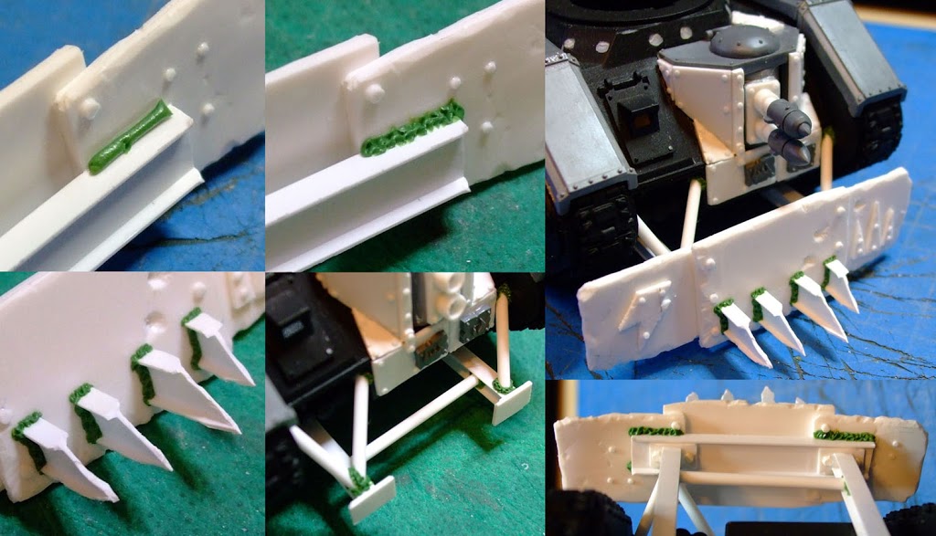
Where rivets couldn’t be used I added weld lines. This includes the I beam on the rear of the ram. A thin roll of GS was added to the join and a sculpting tool with a rounded tip was used to get a ‘rippling’ effect. I am not attempting to create an accurate recreation of welding, more an impression of one. More welding was added to the front spikes and to the mounting steelwork.
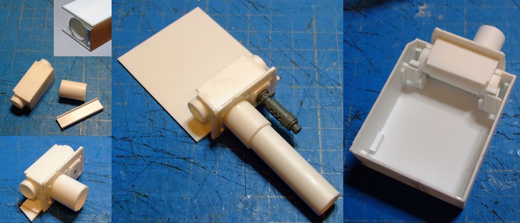
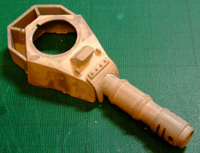
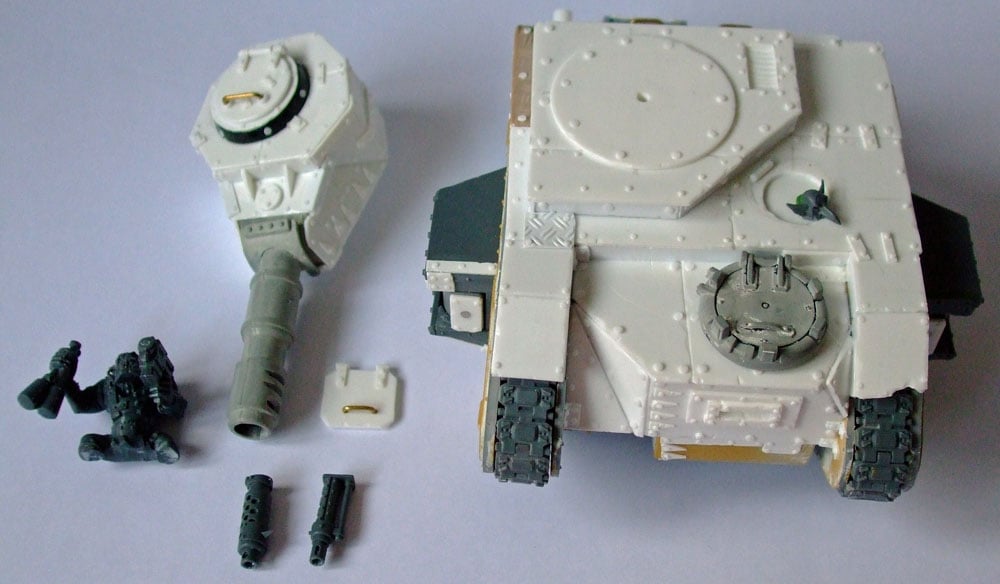
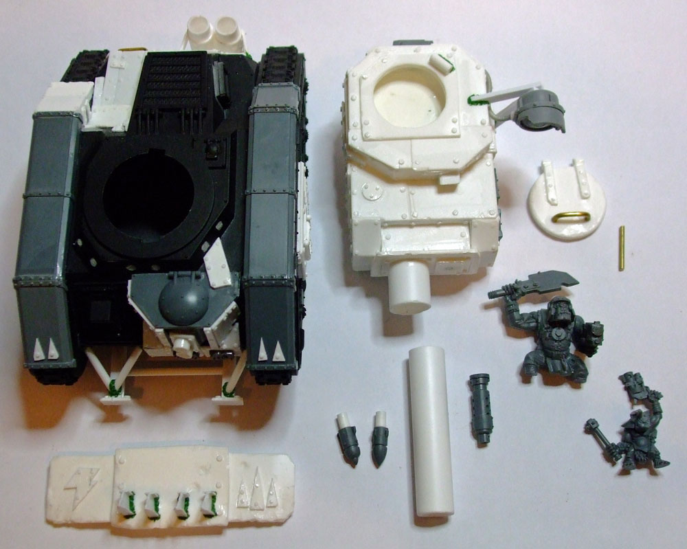
The turret was scratchbuilt around the weapons. I started by building the mantlet incorporating a magnet for the Big Shoota and a length of tube for the Boom Gun. The mantlet determines the size of everything else so has to be done first.
Behind the mantlet is a box shape made of tube and a piece of I beam covered in styrene. The tube will form the hinge for the gun to raise and lower, the I beam pushes this back so it isn’t too close to the mantlet.
The base panel of the turret is then cut with a width to suit the weapon mounting. The ends of the tube are encased inside the turret, but not glued. This allows the tube to turn on its axis but not move in any direction. There are many ways of achieving the same result, I seem to do it differently each time I build a turret so it is best to experiment and see which way you prefer.
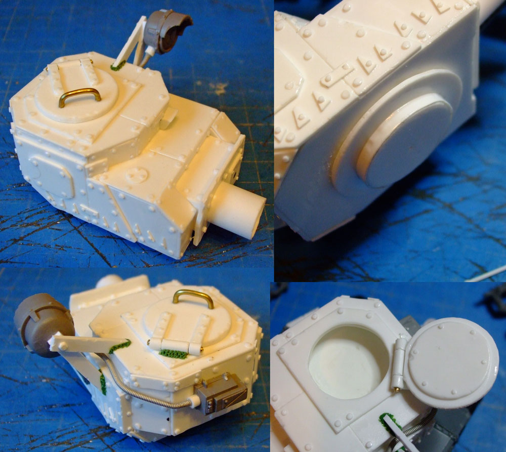
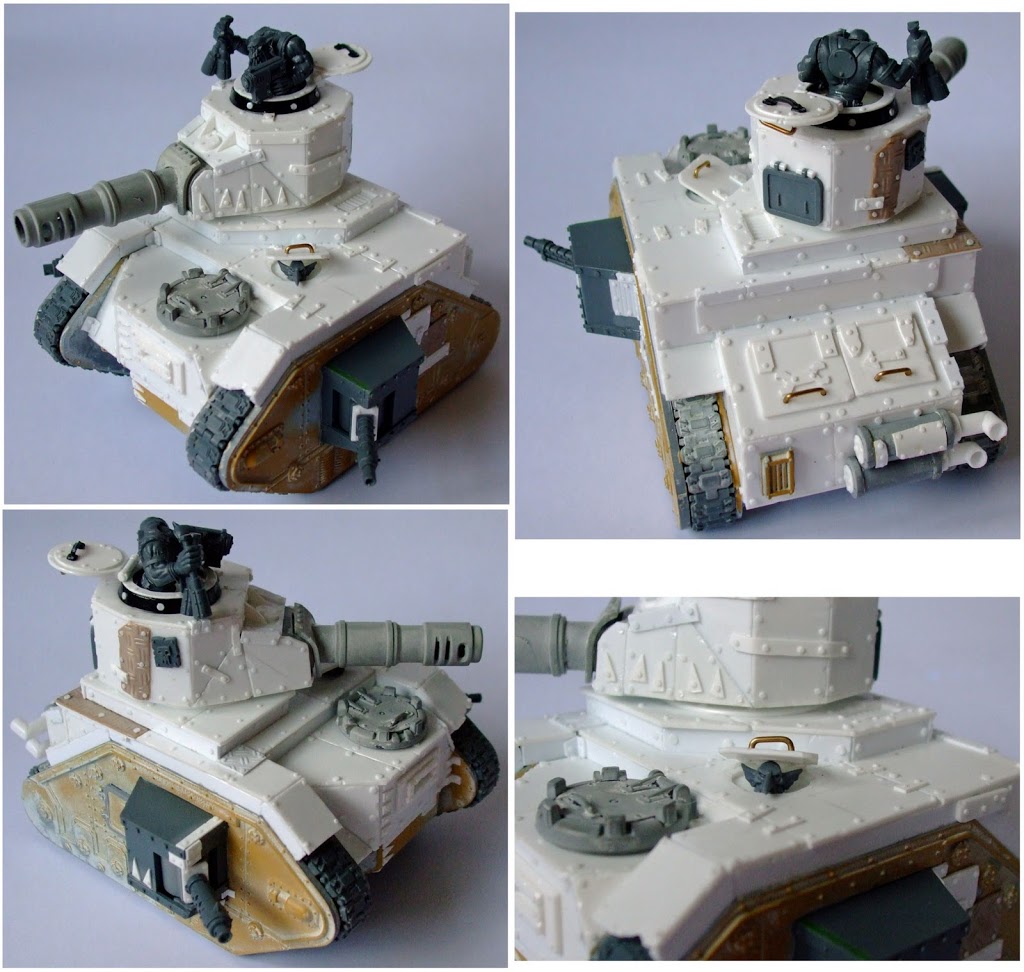
Once the base and sides are in position the rest of the turret is fairly simple. A top was added with another level incorporating a hatch. The front panelling was angled to give plenty of clearance to the mantlet as the gun raises. At the rear I built out an area while removing the lower corners giving a more pleasing look.
The internal diameter of the turret ring was measured and three discs were cut approximately 0.5mm undersize. These were stacked and attached centrally to a larger disc and added to the turret. 0.25 strip was glued around the stack and trimmed, giving the turret a snug fit into the turret ring, easily removable while not being loose.
The turret was detailed with Orky repair work, rivets and dags while a searchlight was added with a Lascannon power pack.
And finally here are the finished Looted Wagons:
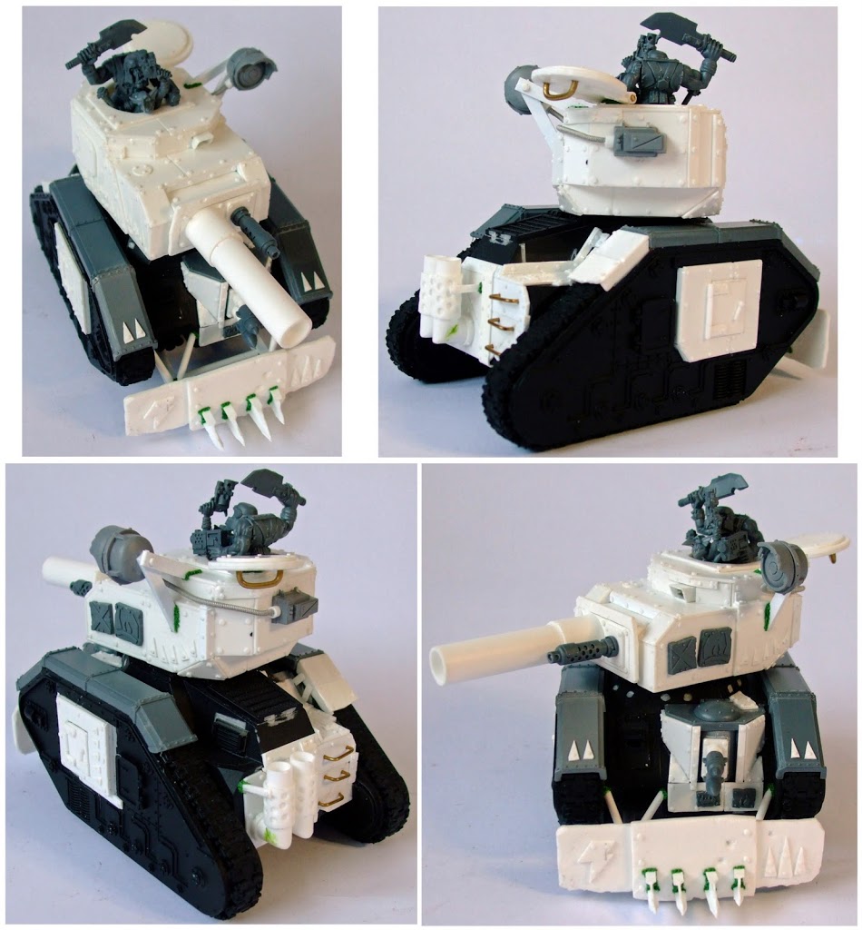
That turned out to be one very long article…congratulations if you got through to the end. I hope it has been of interest and maybe sparked an appetite to do some looting of your own. Please feel free to ask any questions or pop along to Recalcitrant Daze and say hello.
Author: Rictus
Advertisement
