40K HOBBY: One Meks Step-by-Step Guide to Lootin’ – Part Two
7 Minute Read
Dec 18 2011

Advertisement
Continuing my step-by-step article on how I loot vehicles, part two follows the progress of the first Looted Wagon and shows how I went about rebuilding the hull and adding weapons and details.
Looted Wagon 1
During the mock up stage I removed the original Russ engine area and the turret ring; styrene was used to reinforce everything. Styrene was glued into the gap so it was flush with the hull.
Advertisement
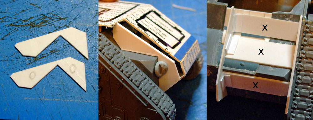
Using the mock up as a guide I cut the side panel for the new engine block out of 1mm sheet. I modified the cut piece until I was happy with the shape and it fitted onto the Russ hull. A second panel was then cut using the first as a template and sanded so it matched the first. After then removing any rivets the first panel was glued to the track unit. Three pieces of styrene cut to the same length (x) were glued in place so the second panel could then be glued up against them, some angle strip was used to reinforce the join and ensure the panel stayed perpendicular to the hull.
1x4mm strip formed the ‘walls’ of the track guards. The end pieces are angled so they meet the central piece. The covers are 0.5mm sheet and textured sheet bent to fit over the profile. 1mm rivets were added (not shown) to the covers in line with the ‘walls’ below.
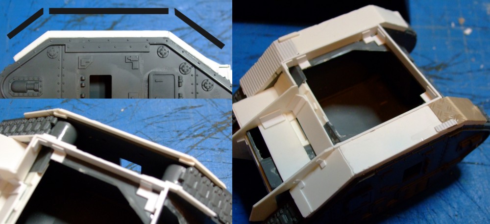
At this stage I also added strip around the top of the hull which the top paneling would sit down.
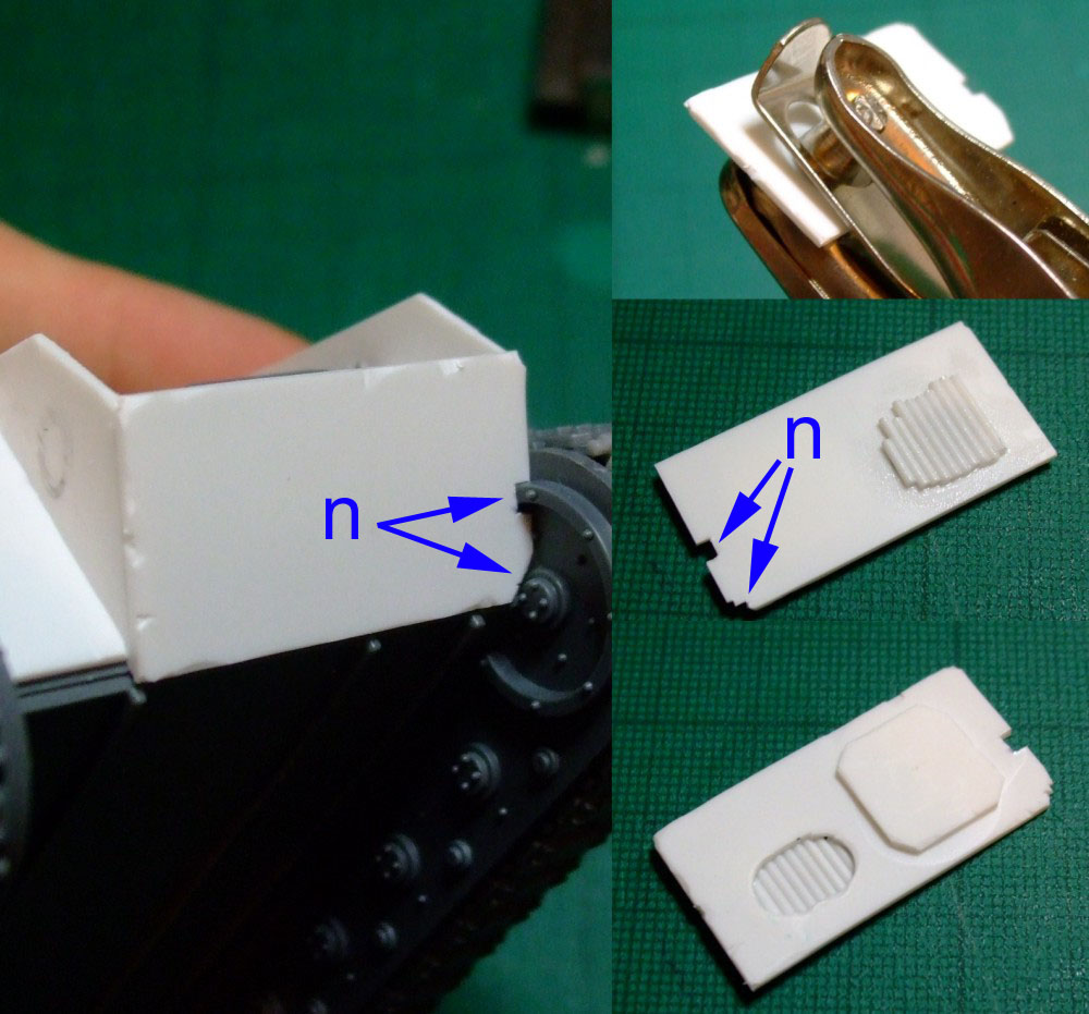
Returning to the rear a lower panel was cut with notches added to suit the detailing on the track unit (‘n’).
A hole punch and knife was used to cut a slot and on the inside face rod was glued so that a vent would be seen from the outer face.
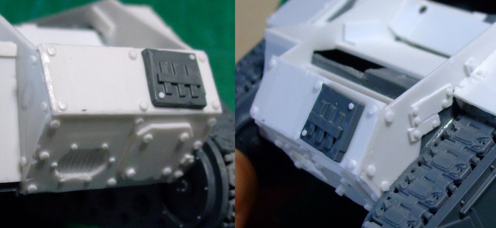
The upper panel came next before the engine block area was detailed with a mix of 1 and 1.6mm rivets, some strips and a glyph.
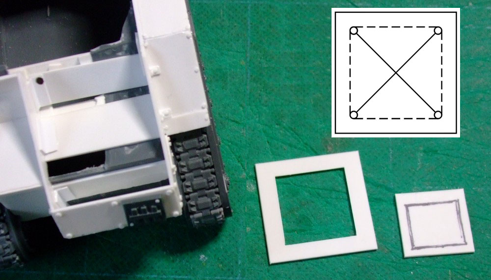
My attention then turned to the top panel and engine access hatch. A piece was cut which fit the area and flush with the top. An area was then cut out; there are many ways to do this but I drilled near each corner then cut a cross pattern between the holes, after scoring horizontally and vertically you can bend and snap each section out. A knife and file can be used to neaten the hole. The access hatch was cut to fit the hole but with a 3mm gap at the top.
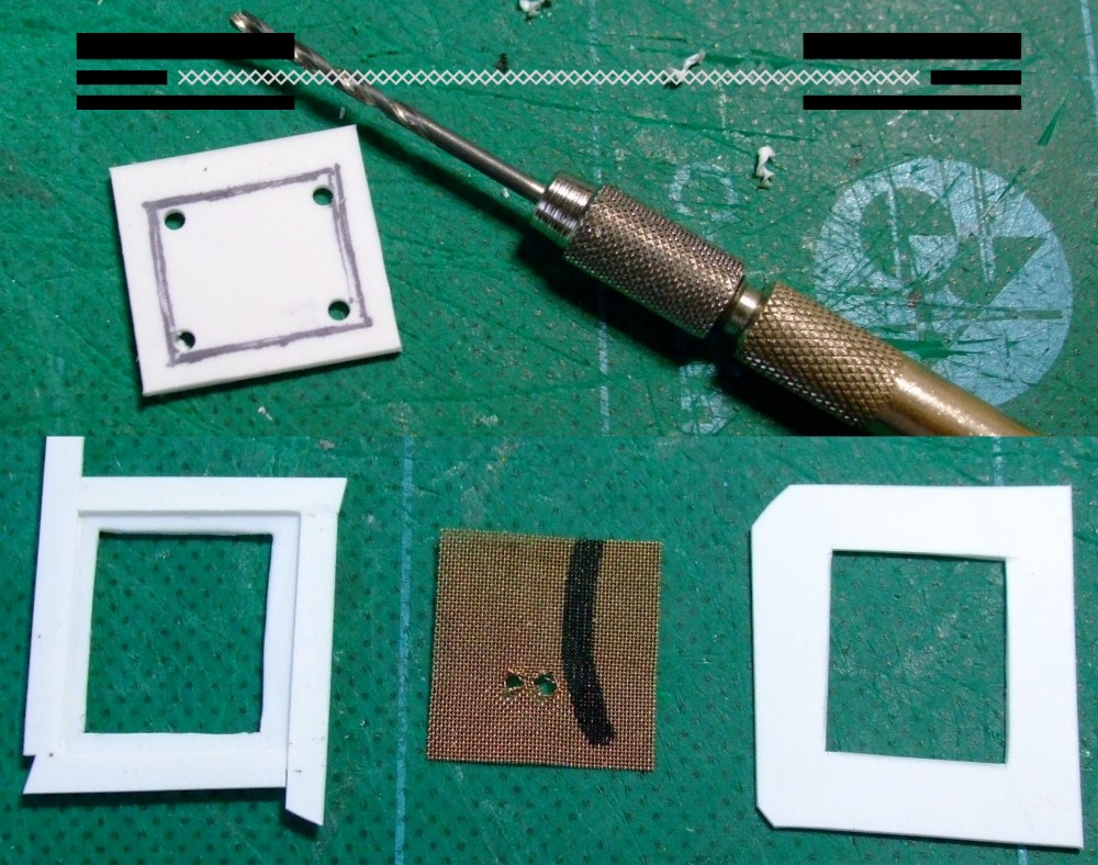
I wanted the center of the access hatch to be mesh; this will be sandwiched between styrene layers as gluing mesh isn’t easy so additionally securing it this way is often a good choice.
A hole was cut into the access hatch front panel before 0.5mm styrene was glued onto the inside face leaving 2-3mm free round the hole. A piece of small scale mesh is cut to fit this frame and finally some 0.5mm sheet is cut larger than the hatch front but with a matching hole. The mesh was superglued into the frame and the rear panel glued in place so the holes lined up. Excess material was cut away and the piece distressed.
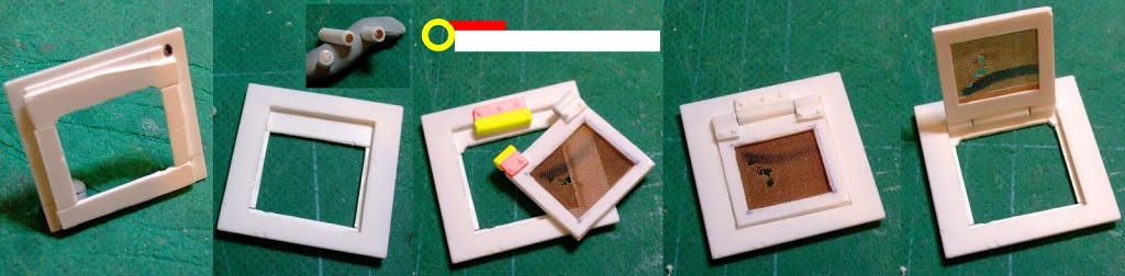
On the inside face of the larger panel 0.5 styrene was added keeping well clear of the edges. The centre was cut out. Styrene was glued onto the inside face to form a ledge for the hatch to sit on. Adding the 0.5mm first means the 2mm thick hatch will not be too proud. The ledge is deeper at the top for the hinge.
3.2mm tube was cut for the hinge. The central hole was opened to 2mm before the length was cut into three pieces to form the hinge knuckle pieces (yellow). 2mm diameter magnets were glued into the ends where the hinge parts meet.
The hatch and hinge were positioned in the hole and the hatch sanded back so they comfortably fit. Adding glue directly to the hinge will likely result in everything sticking together, instead small pieces of styrene are used as the leaf of the hinge (red). One end is angled so it fits against the curved surface. The leaf pieces were then carefully glued in place securing the tube to the hatch. When all three were added the hatch can be gently removed and more glue can be added to secure everything.
Using the magnets allows the hatch to stay in place but open and close freely.
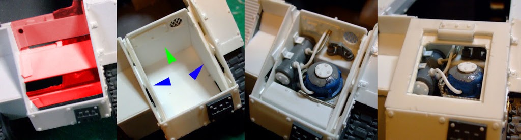
The engine detail can now be added. It was best to leave the engine until the top panel was done as I could then drop the panel in place to check everything fitted. It also allows you to see what can be seen through the open hatch.
The first job was cutting out areas highlighted in red which was no longer needed and now just got in the way. Side panels (blue) were added offset using offcuts from the outer panels giving a thicker wall. The forward panel (green) was detailed and fixed in place along with a base piece. The ‘engine’ is simply a mix of pieces including the original exhausts, a Guard searchlight, styrene rod, tubing etc. Basically anything that looked interesting got thrown in.
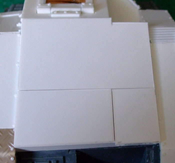
For the top a single piece of styrene was cut with a slight overhang. To make it more interesting it was cut into three pieces which were trimmed so that the outer edges didn’t perfectly line up. The three pieces were distressed along all the edges.
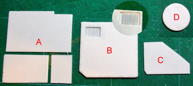
The basic components of the top are (A) the three lower panels, (B) mid plate made from two pieces of 1mm styrene glued together with rod glued into a clearance hole cut into the bottom piece to form a vent, (C) top plate and (D) hatch.
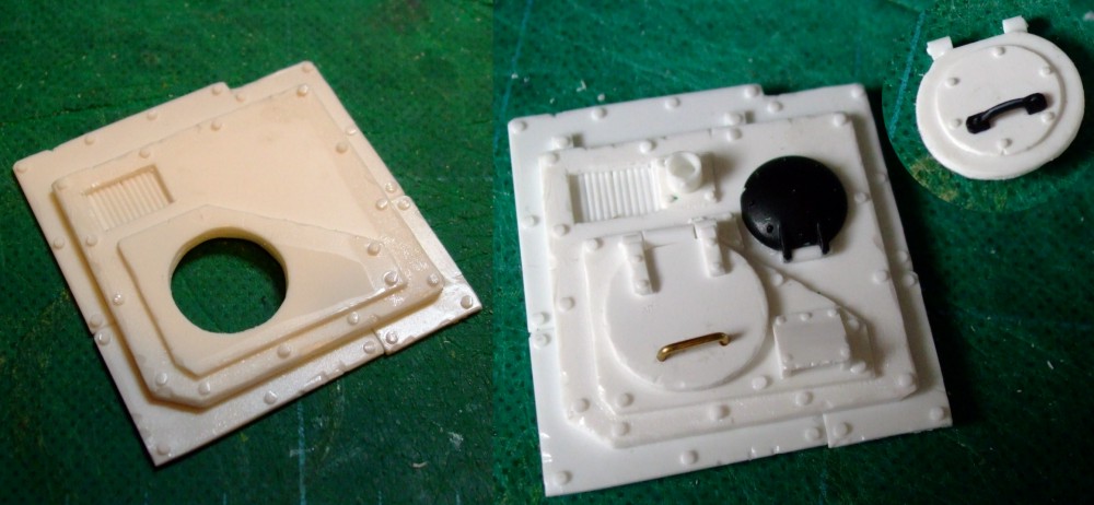
A hole was cut into the top plate and continued through the mid plate after the top plate was glued to it. A clearance hole was cut into the lower panels before they were glued to the upper assembly.
The hatch was detailed with handles and an internal panel. The hinge is simply made from 2mm rod. The hatch will be glued into position once the tank has been painted. Other details were used to add interest, namely a second hatch using the originally Russ hull weapon piece, a viewing port at the front and a base for a banner pole at the read.
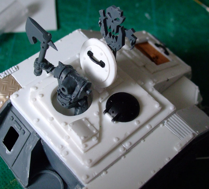
The top plate fitted in place with the banner pole and hatch in position. A Black Reach Ork had his legs cut down and sits in the hatch, on the inside styrene was glued below the hole for him to sit on.
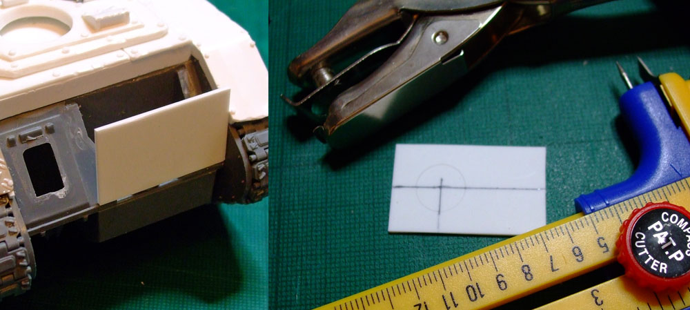
To mount the Boomgun styrene was cut to fit on the front. An 11mm circle was scored onto the panel, using a hole punch and a knife the hole was cut out until an 11.1mm tube fitted.
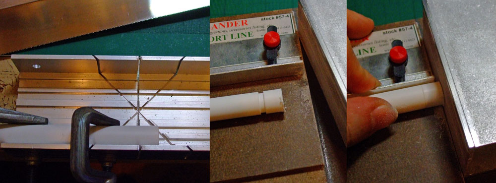
The Boomgun will use several pieces of tube and the ends of these will need to be square so everything fits together straight. The tubes are cut with a razor saw and a mitre block before using the True Sander to square the ends. For small lengths of tube I put them and a longer length on a smaller tube as it makes it easier to push the small piece into the sanding block.
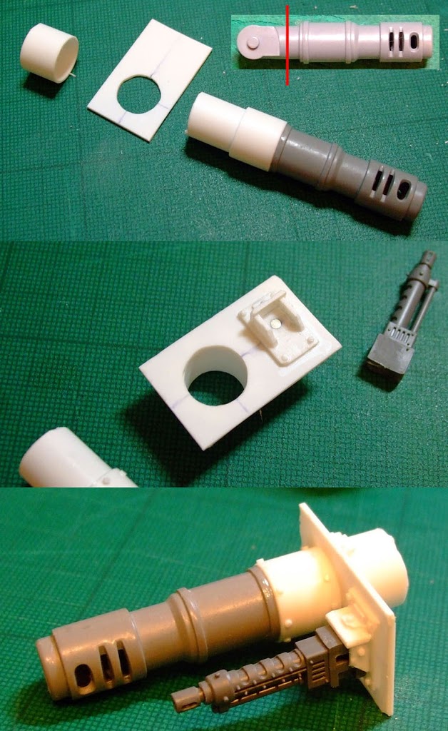
Two short lengths of 12.7mm tube were cut and sanded. One piece glued to a cut down battlecannon (it fits perfectly over the battlecannon at this point) and the other piece was glued to the rear of the panel in line with the hole. A length of 11.1mm tube was glued into the rear of the battlecannon.
A big shoota was cut down and a 2mm magnet mounted in the rear. A small rectangle of 1mm styrene incorporating a magnet added. Small styrene strips were added while taking care not to glue them to the Big Shoota.
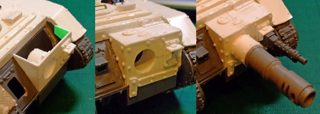
The finished panel was glued in position using engineer squares to ensure the panel was upright and flush with the front of the hull. Offcuts were used to reinforce the join and to fill in the side (green). Pieces of styrene were cut to suit the side and the top before the area was detailed.
Here ends Part Two. In Part Three the second and third Looted Wagons are built and pictures of the three finished builds are shown. If you have any questions about Part Two please post them up or drop into Recalcitrant Daze for a look round.
Author: Rictus
Advertisement